
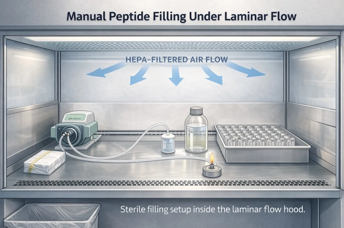
The drawing above illustrates the laminar flow workstation setup seen in the accompanying video. This is the environment where the peptide solution is prepared and the vials are manually filled.
In this post I describe the method and equipment used, while the following post shows the actual factory footage of the process in action.
In the video, the workflow appears to move between two laminar flow workstations. One workstation is used for solution preparation and sterile filtration, while the second workstation is used for manual filling of the vials under sterile airflow.
The diagram therefore represents a general illustration of the sterile workstation environment used for these stages, rather than an exact floor plan of the facility.
Below is the process shown in the video.
1. Preparation of the peptide solution
The video begins with the peptide solution being prepared inside a laminar flow hood.
A container holding the solution is positioned inside the sterile workspace. This container holds the final liquid formulation that will later be filtered and dispensed into vials.
The solution typically contains:
the raw peptide itself (API)
sterile water or buffer
added stabilisers and excipients to support the formulation during lyophilisation
Preparing the solution inside the hood helps reduce exposure to airborne contamination.
2. Sterile filtration setup
The next step shown is the preparation of the sterile filtration system.
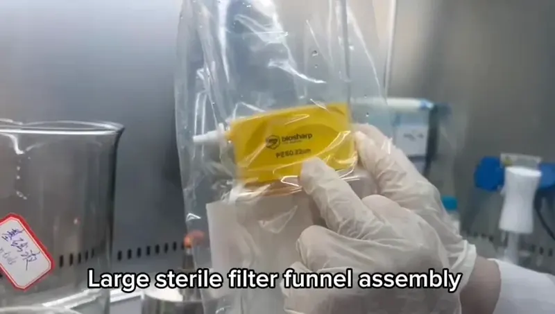
In the video you can see a yellow disc filter still inside sterile packaging.
This is a 0.22 micron sterile filter, which is widely used for sterilising liquid formulations.
The filter removes:
bacteria
microbial contaminants
particulate matter
This filtration stage is one of the final sterility barriers before filling begins.
3. Assembly of the filtration system
The operator removes the filter from its sterile packaging and connects it to the solution container.
The filtration system consists of:
the solution container
the sterile filter
tubing leading to a receiving container
The solution must pass through the 0.22 micron membrane before it reaches the final container used for filling.
4. Sterile filtration of the solution
The peptide solution is then filtered through the 0.22 micron membrane.
The filtered solution flows into a clean receiving container positioned beneath the filter assembly.
At this stage the solution has passed through the sterile barrier and is ready to be transferred to the filling system.
5.Labelling the container
After filtration the container is marked with a pen.
This appears to be a simple visual reference mark used during the filling process.
6.Transfer to the filling workstation
The video then moves to a second laminar flow hood.
This second workstation contains the equipment used for manual filling.
Visible in this hood are:
a stainless steel work surface
a peristaltic pump
sterile tubing
an alcohol burner
This hood is used specifically for the open vial filling stage.
7.Laminar airflow protection
Both workstations operate as laminar flow cabinets.
A laminar flow hood pushes HEPA filtered air downward across the work surface in a smooth, uniform flow.
This continuous stream of clean air prevents airborne particles such as:
dust
microbes
environmental contaminants
from settling onto exposed containers or open vials.
This controlled airflow is essential during the stage when the vials are open.
8.Flame sterilisation
Next to the workstation a small alcohol burner is visible.
Before handling the solution container, the operator briefly passes the bottle neck near the flame.
This technique is known as flame sterilisation and is commonly used in microbiology and aseptic handling.
The heat helps destroy microorganisms that may be present on exposed surfaces such as:
bottle openings
metal tools
tweezers
This helps maintain sterile conditions while manipulating containers inside the hood.
9. Peristaltic pump setup
The green machine visible in the footage is a peristaltic pump.
Peristaltic pumps move liquid through flexible tubing by compressing the tubing with rotating rollers.
This design offers an important advantage:
the liquid never contacts the pump mechanism itself.
Instead, the solution only touches the sterile tubing.
Because the tubing can be single use and sterile, this design greatly reduces contamination risk.
10. Connecting the sterile tubing
Clear sterile tubing is attached to the pump and connected to the solution container.
The tubing forms a sterile pathway that carries the peptide solution from the container to the filling outlet.
Before filling begins, the system must be primed.
11. Priming the tubing
Priming removes air bubbles from the tubing system.
Air inside the tubing could lead to:
incorrect fill volumes
inconsistent dosing
foaming in the vials
To prevent this, the operator runs solution through the tubing until the flow becomes stable.
This ensures the entire fluid path contains liquid before filling begins.
12.Transfer Cabinet / Pass-Through Box
The video briefly shows a transfer cabinet (pass-through box) containing wrapped trays of vials, tubing sets, and pipette equipment. These cabinets are used to move sterile materials into the cleanroom while minimizing contamination risk. Materials are placed into the cabinet from outside the cleanroom and then retrieved from the sterile side before work begins.
13.Preparing the vial tray
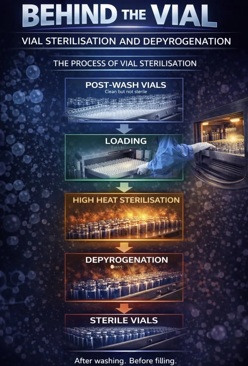
A stainless steel tray containing many empty glass vials arranged in a grid is placed inside the hood.
These vials are typically made from Type I borosilicate glass, which is commonly used because it is:
chemically inert
resistant to thermal shock
compatible with pharmaceutical formulations
The tray keeps the vials stable and organised during the manual filling process.
14.Manual filling of the vials
Once the tubing has been primed and the system is running smoothly, manual filling begins.
The dispensing tube is positioned above the tray of vials while the peristaltic pump controls the flow of liquid.
In this particular setup:
the pump controls the volume delivered
the operator controls the position of the dispensing tube
The operator moves the tubing across rows of vials so that each vial receives the programmed volume of solution.
15.Monitoring fill consistency
During filling the operator monitors the process visually.
They may check:
the liquid level in the vials
the stability of the flow
the overall consistency of the filling process
In large automated production lines this step is often handled by camera based inspection systems, but in smaller batch production it is typically checked visually by the operator.
Manual filling is often dismissed as less precise, but accuracy depends less on whether the process is manual or automated in theory, and more on pump calibration, line setup, operator technique, and in process checks. In this setup, the operator guides the tubing by hand, but the peristaltic pump regulates the volume, allowing a consistent amount of solution to be dispensed into each vial.
Although the stoppering step itself is not shown, later footage shows the vials to already have stoppers partially inserted. These are not fully seated. The stoppers sit loosely in the vial neck to protect the opening while still allowing vapour to escape during freeze drying before final sealing. They are shown being marked with a pen, likely as a temporary identifier or reference during handling. The tray is then moved on toward the next stage which is the lyophilisation stage.
The next post shows the video walkthrough of the entire process, from filtration and pump setup through to the manual filling of the vial trays.

Comments